 |
|
|
|
[Contents] | [Index] |
Cooperation with: D. Zeitz (ALSTOM (Switzerland) Ltd., Baden)
Supported by: ALSTOM (Switzerland) Ltd., Baden
Description:
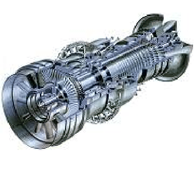
Like in many other process industries, the numerical process simulation plays an important role in today's gas turbine engineering. Here, the simulation is used for process design, safety management, efficient operation and control of single components of industrial gas turbines (Fig. 1) as well as entire combined-cycle power plants. In complex and highly nonlinear modeling, large-scale simulation problems may arise. Thus, using concentrated physical models, high-dimensional systems of nonlinear or differential-algebraic equations (DAEs) have to be solved in static or dynamic process simulation, respectively. For their solution, robust and fast numerical simulation tools are needed.
At the Weierstrass Institute we have developed a simulation concept which exploits the modular structure of the process, that in most cases corresponds to the hierarchical unit structure of the underlying plant (see, e.g., the right part of Fig. 2). With it the corresponding system of equations is structured into subsystems according to the units and can be portioned into blocks, which can then be treated almost concurrently within appropriately modified numerical methods. The approach is based on divide and conquer techniques and has been implemented in the Block Oriented Process simulator BOP that uses an own compiler to generate a hierarchically structured data interface from a process description with its modeling language MLPE (Modeling Language for Process Engineering). Within this approach a block-partitioned system of equations
In the period under report, the simulation approach of BOP was successfully adapted to the process simulation of industrial gas turbines. Improvements of the numerical methods in combination with a more efficient implementation have led to a remarkable speedup of simulation time in this field. Simulations of numerous industrial gas turbine problems have shown that the simulation runs with BOP are between two and five times faster than those performed with the Aspen Custom ModelerTM (ACM), a worldwide leading commercial simulation tool of Aspen Technology (USA). For about 95 % of these simulation problems, the steady state solution was found with the standard numerical control parameters of the BOP solver. In almost all of the remaining cases, the solution was found after modification of some control parameters. After the implementation of a subset of the modeling language of ACM, BOP can now handle three different types of model descriptions. Beside a description with MLPE, descriptions with language subsets of SPEEDUP and ACM are possible as well, where the two subsets correlate to the scope of MLPE. Additionally, we implemented techniques that allow an exchange of parameters (fixed) and variables (free) of a simulated process without the necessity either to generate a new data interface or to recompile model functions before a new simulation run of the modified sample can be performed. This holds also for repeated fixed-free changes.
![\makeatletter
\@ZweiProjektbilderNocap[h]{0.4\textwidth}{alstom_supergau_example.eps}{alstom_slide2.eps}
\makeatother](img454.gif) |
As a result of these achievements, a license of the simulator has been sold to ALSTOM (Switzerland) Ltd., a leading gas turbine producer. Currently, BOP is used here for single steady state simulation as well as parameter verification problems. It runs under the Windows XP operating system on PCs, where it is called by the graphical user interface SuperGAU (see the left part of Fig. 2) developed by our cooperation partner at ALSTOM Power.
Lately, a second contract between WIAS and ALSTOM has been signed which aims at an enlargement of the functionality of BOP as well as a further adaptation to industrial needs. In this context we started the implementation of advanced elements of the modeling language of ACM, which are currently not included in MLPE. Beside this we provided the simulator with a Java Native Interface (JNI) and a binary input/output. The interface is needed for a direct data transfer between the Java GUI and the simulator, now realized by a dynamic link library.
The numerical methods realized within BOP require a repeated solution of linear systems with the same pattern structure of sparse, unsymmetric coefficient matrices. This is done with an adapted version of our linear solver GSPAR, [3], which uses a modified Gaussian elimination with column reordering, partial pivoting, and pseudo code generation for refactorization (so-called fast second factorization). The basic (non hierarchical) version can be used as a stand-alone linear solver as well. Its newest version GSPAR2 has recently been compared with the solver UMFPACK Version 4.1 (Apr. 30, 2003) (Timothy A. Davis, CISE Department, University of Florida, USA). Results concerning the computing time on an HP AlphaServer GS1280 7/1150 are given in Table 1. For the linear systems with matrices arising from different real-world applications, the numbers N and NNZ denote the order and the number of nonzeros of the coefficient matrix, respectively.
References:
|
|
|
[Contents] | [Index] |